
greenshiftspraysystems@gmail.com
+91-9830983311
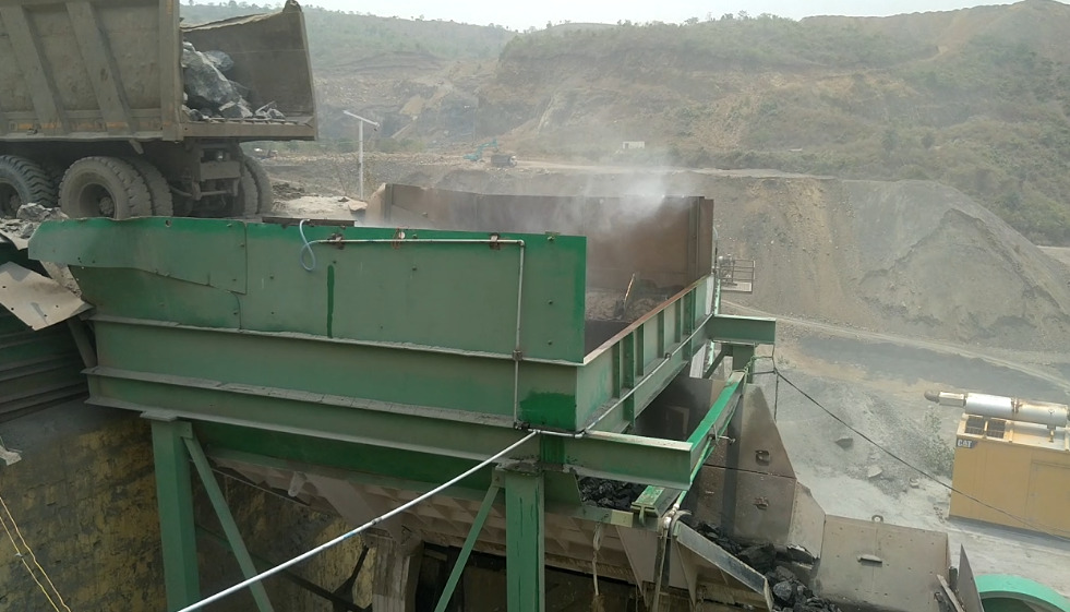
A
conveyor transfer point can turn a clean work area into a dust cloud within
seconds. Uncontrolled industrial dust reduces visibility, wears equipment,
causes product loss, increases clean-up work, and exposes workers to harmful
particles. Some materials also create combustible-dust fire or explosion risks.
An industrial
dust suppression system project connects the dust source to the right
engineering solution. It defines targets, checks site data, compares
technologies, and estimates lifecycle costs, and sets measurable acceptance
tests. A sound covers design, installation, commissioning, safety, and
long-term performance.
Project Goals
Quantify the cost of uncontrolled dust
Start
with site records, not broad industry averages. Review dust-related downtime,
maintenance calls, filter changes, clean-up hours, product rejects, complaints,
and production interruptions.
Estimate
material loss at crushers, screens, conveyors, silos, transfer points, stockpiles,
and loading areas. Separate one-time capital costs from recurring expenses such
as water, power, additives, labour, spare parts, repairs, and waste disposal.
Set measurable health and production targets
Define
what the completed system must achieve. Targets may include lower airborne
dust, better visibility, less surface build up, lower worker exposure, reduced
visible emissions, and fewer clean-up events.
Identify
dusty tasks and occupied work areas. Check occupational exposure limits,
environmental rules, fire codes, and site permits for the material and
location. Set acceptance limits for dust concentration, moisture addition,
water use, product quality, and runoff. Screen for combustible dust when the material
may burn or explode as a suspended cloud.
Site Data
Map sources, airflow, and exposure paths
Build a
process flow diagram that shows every dust-generating activity. Mark belt
transfers, impact zones, discharge points, open storage, truck routes, doors,
fans, and occupied workstations.
Walk the
site during normal and peak production. Record cross-drafts, building openings,
enclosure gaps, and airflow direction. Photos of dust plumes and settled
deposits can reveal control failures that drawings miss. Note access limits,
since tight spaces may affect nozzle positions, duct routes, platforms, and
maintenance access.
Test material and utility conditions
Particle-size
data helps show whether the main concern is inhalable, reparable, or larger
settled dust. Also record moisture, temperature, bulk density, abrasiveness,
solubility, and resistance to wetting.
Water may
affect product quality, storage life, shipping weight, belt grip, or downstream
processing. Test additives for chemical compatibility and possible effects on
soil, wastewater, equipment, and workers.
Record
minimum, normal, and peak throughput, belt speed, drop height, belt width,
crusher capacity, and loading rate. Confirm water pressure, flow, quality,
storage, and temperature. Check electrical capacity, hazardous-area ratings,
compressed air, drainage, communications, freezing weather, wind, rain, and
heat.
Technology Selection
Compare wet, dry, and hybrid controls
Water
sprays suit many conveyors, transfer points, stockpiles, haul roads, and open
loading areas when added moisture is acceptable. Foam can improve wetting and
coverage while reducing liquid demand. Chemical agents, such as surfactants or
binders, may help difficult materials, but their environmental and product
effects need testing.
Local
exhaust ventilation with filtration often fits enclosed crushers, screens,
bins, and fine-dust sources where water cannot enter the process. A hybrid
design may combine enclosures, extraction, filtration, and targeted wetting.
The study should compare control results, utility demand, maintenance, product
impact, and total cost before selecting equipment.
Match nozzles to dust and process conditions
Droplet
size must suit the dust particle, airflow, material speed, and source shape.
Hydraulic nozzles may fit basic wetting, while air-assisted or compressed-air
atomization can produce finer droplets for enclosed sources.
Check
spray angle, overlap, pressure, flow, wear, and clogging risk. Confirm
performance with flow tests and manufacturer data at the actual operating
pressure. Add strainers, isolation valves, flushing points, and spare nozzles
where dirty water or abrasive solids are likely.
Engineering Design and Safety Controls
Size pumps, piping, air, and storage
Calculate
liquid flow for each suppression zone, then size pumps for total flow,
elevation, static head, friction loss, and required pressure. Check pipe
velocity, pressure drop, flushing capacity, insulation, and freeze protection.
Size
tanks for normal demand, refill time, water quality, and emergency reserve.
Compressed-air systems need enough flow and receiver capacity for all zones
operating together. Include future production increases and simultaneous
operation in the design basis.
Add controls and hazard safeguards
Link suppression
to conveyors, crushers, feeders, screens, or loading equipment. Flow, pressure,
tank level, and pump-status signals can identify blocked nozzles, leaks, empty
tanks, and pump failures.
Control
logic should stop water when process flow stops or unsafe conditions occur.
Include low-pressure, high-pressure, low-level, leak, and blocked-nozzle
alarms. Local controls should support testing and maintenance. Log alarms, set
points, water use, and run time.
Review
worker safety, electrical rules, machinery safeguards, and environmental
permits. If dust can explode, coordinate wet control with ignition prevention,
grounding, bonding, explosion venting, isolation, and fire protection. Provide
guards, lockout points, safe platforms, chemical handling procedures, eyewash
stations, safety data sheets, and controls for contaminated runoff or sludge.
Project Economics
Build a complete cost model
Capital
costs may include surveys, laboratory work, engineering, permits, project
management, pumps, tanks, valves, piping, nozzles, filters, controls,
electrical work, structures, enclosures, drainage, insulation, heat tracing,
and installation.
Operating
costs include water, electricity, compressed air, additives, inspections,
calibration, labour, spare parts, waste handling, planned maintenance, and
unplanned repairs. Include commissioning and periodic performance testing so
the model reflects the full project life.
Measure savings and financial risk
Compare
baseline and post-project clean-up hours, dust-related downtime, filter use,
equipment maintenance, product loss, and rejects. Document changes in
complaints, visibility, exposure results, and regulatory risk where records
support those benefits.
Present
installed cost, annual operating cost, annual savings, simple payback, and
projected cash flow. Test low, expected, and high cases for production, dust
reduction, water price, additive use, energy cost, downtime savings, and
equipment life. State assumptions, exclusions, data sources, unresolved risks,
and contingency clearly.
Commissioning and Performance Evaluation
Install without disrupting safe production
Complete
detailed engineering, procurement, fabrication checks, and pre-installation
inspections before field work. Plan shutdowns, lifting, hot work, electrical
isolation, access, and weather limits around production needs.
Verify
nozzle locations, supports, drainage, clearances, enclosure joints, and service
access before start-up. Use inspection and test plans for pressure tests,
electrical checks, control-panel tests, and instrument calibration. Train
operators and maintenance staff before handover.
Prove results under real conditions
Flush and
clean piping before installing exact nozzles. Check tank levels, pump rotation,
pressure, flow, valves, alarms, and interlocks. Test each zone alone, then test
all required zones together.
Run the
system at minimum, normal, and peak production. Check spray coverage,
overspray, leaks, build up, freezing risk, and material behaviour. Compare
baseline and post-installation dust results using consistent sampling methods.
Track
airborne dust, visible emissions, deposition, worker exposure, water use,
additive use, energy, downtime, and maintenance frequency. Record production
rate, weather, sampling locations, calibration status, and operating settings.
Set review dates and trigger levels for changes to nozzle flow, pressure,
chemical concentration, enclosure design, or ventilation balance.
Conclusion
A strong
industrial dust suppression system project begins with verified site data,
material testing, and clear performance targets. It then balances dust
reduction with moisture limits, product quality, utility supply, maintenance,
worker safety and environmental duties.
The final
project package should contain:
The best
system is not the one that uses the most water or equipment. It is the one that
controls dust at its source, runs reliably, protects workers and products, and
produces measured savings. Approve the project when its design, costs, safety
controls, and test results can all withstand a detailed site review. Greenshift
Engineering for piping of special spray system is an one stop solution for
Industrial dust suppression.